A Nicer Voltmeter Clock
Sometimes, electronic circuit design is mostly about wood
May 16, 202671ShareBack in 2019, I built a simple voltmeter clock:
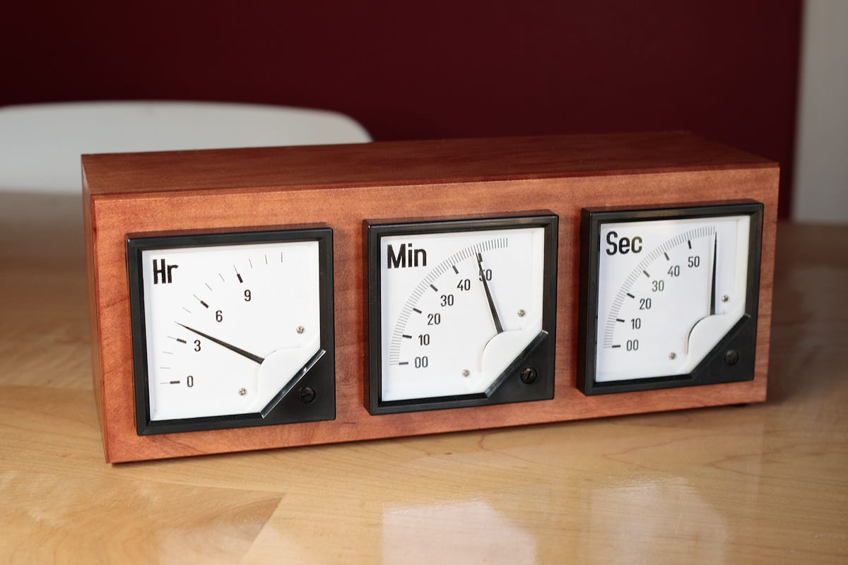
As the name implies, these clocks use analog panel voltmeters instead of traditional clock faces to display time. I didn’t come up with the idea, so I never really blogged about the design; I just built one and kept it on my office desk.
The idea endures, but most of the designs I see on the internet are needlessly complicated and not all that pretty, so when I decided to build a revised design, I figured it might be good to document it better. The process started with a rough mockup in a 3D design program:
For this version of the meter clock, I opted to use three generic, 90° panel voltmeters from Amazon (link, about $9). I disassembled them, took careful measurements of the faces, and then printed replacement decals on adhesive paper. Printable PDF templates can be found here.
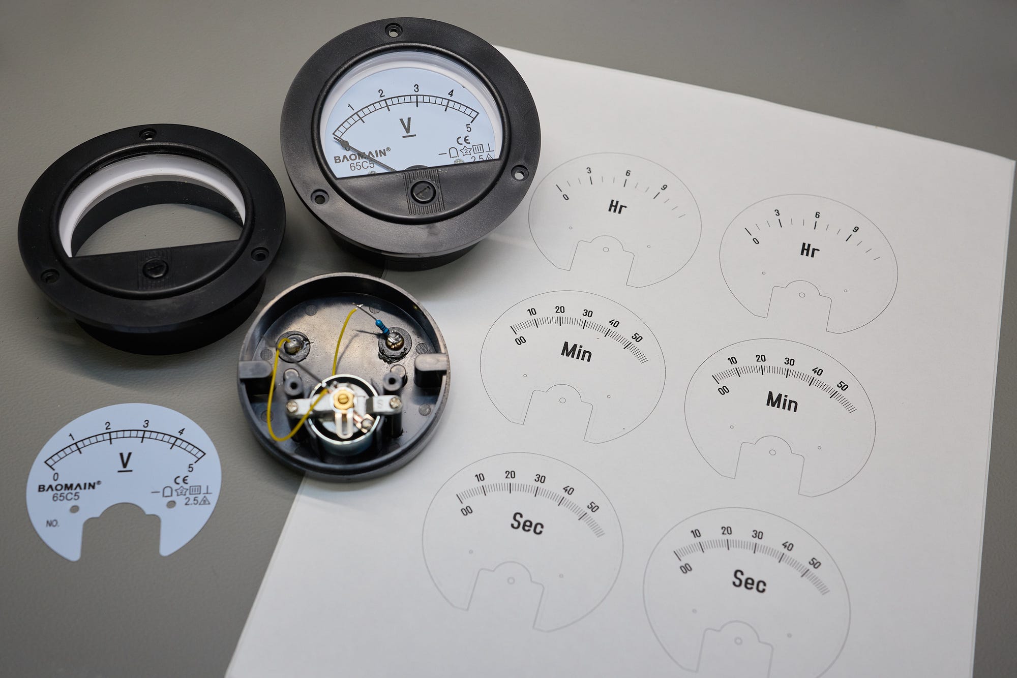
Note that the new hour gauge has 13 divisions, from 0 to 12, while the minute and second templates have 61 divisions, from 00 to 60. This is because I wanted to implement continuous motion for each hand; this meant that at 11:30, the hour dial couldn’t be just stuck at 11; it needed to be moving toward the twelfth division, even if it was never to reach it.
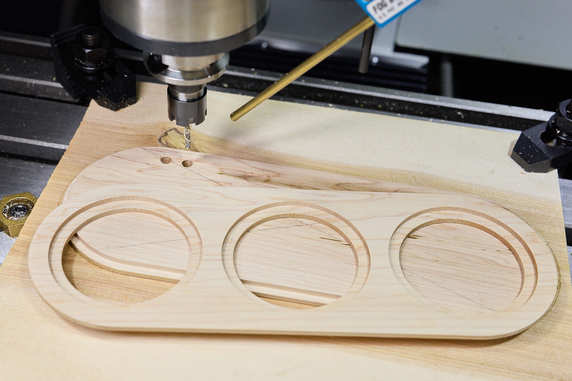
In addition to a host of other problems, the cheap “Baomain 65C5” meters I’m using have a rather hideous plastic flange. I decided to hide this flange from view and use a recessed decorative pattern to keep the front panel interesting. This made it more expedient to cut the front and back on a CNC mill instead of building the enclosure by hand (as I did for version 1):
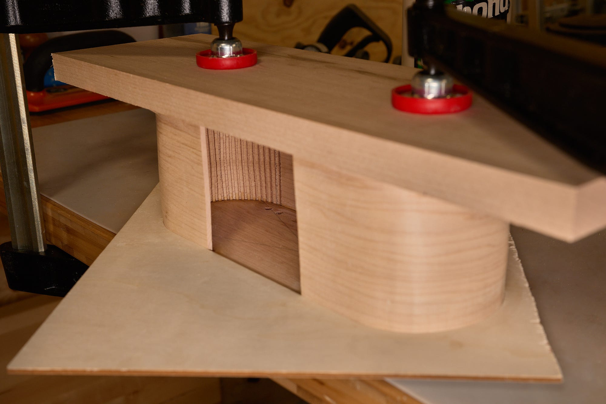
The rounded side wall posed a very different challenge. For a seamless appearance, I needed to do bend a flat piece of wood using a shaped template. To pull this off without a steam bending jig, I had to cut a series of internal notches on the side wall. This allowed the wood to flex more easily:
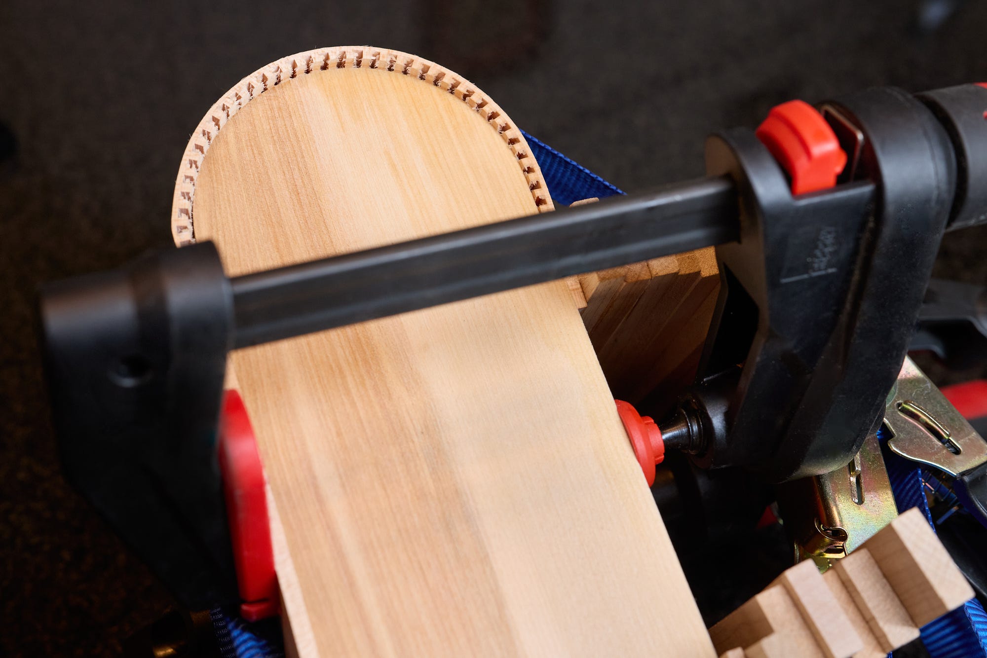
The wood had to be moistened, clamped, and then allowed to dry. After a couple of days, I glued the curved side wall to the front and back faces, relying on another template cut out of scrap plywood to get a precise fit without any more gymnastics with clamps and ratchet straps:
Anyway — here’s the assembled piece after sanding and a coat of nitrocellulose lacquer:
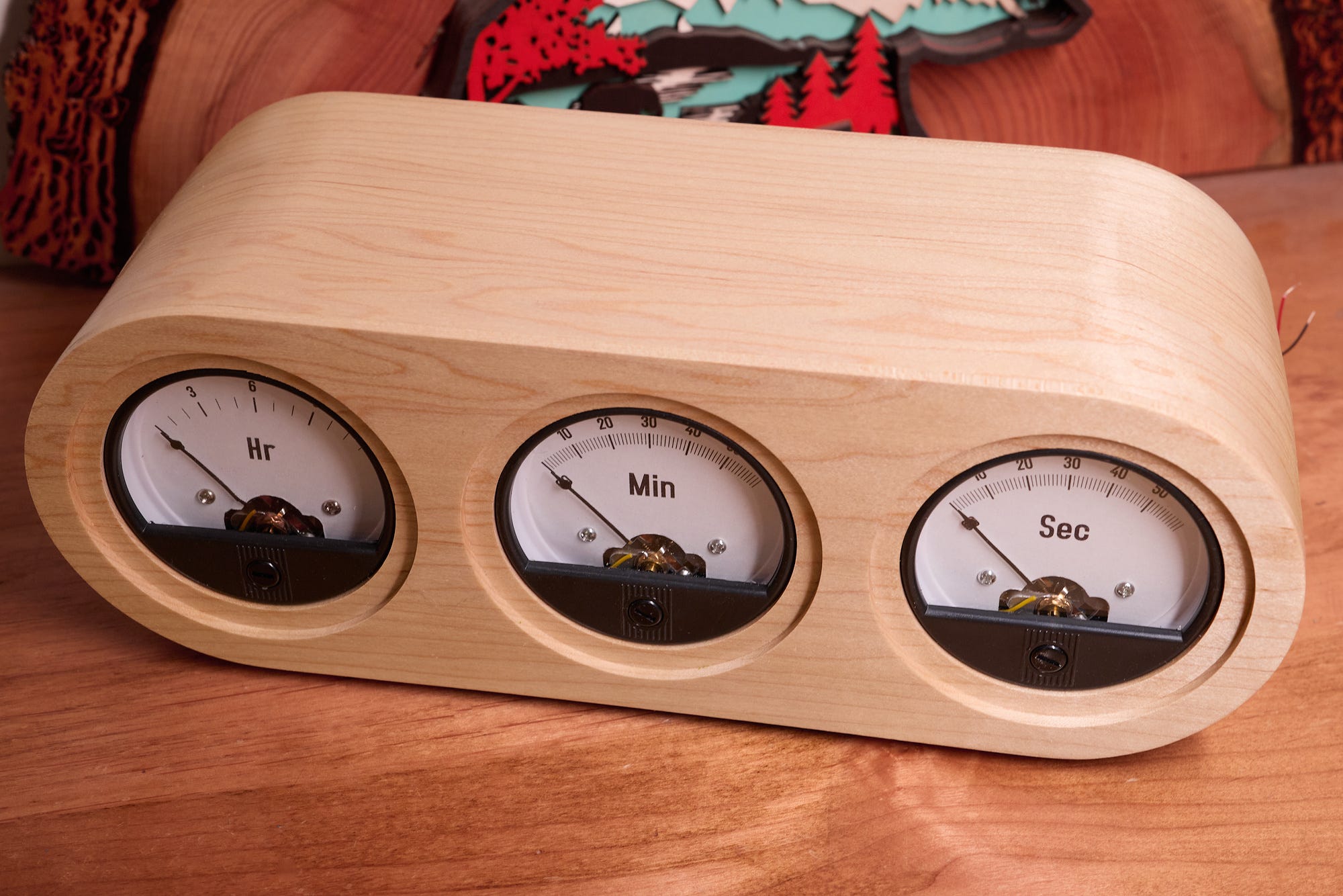
Not bad, right?
The circuit is far less interesting and took just an hour or so: I grabbed the venerable AVR128DB28 MCU, powered it off a wall wart, interfaced it to an 8 MHz crystal (ECS-80-18-4X-CKM). A 32.768 kHz crystal would also do. The panels are connected to three digital output pins (PC0, PC1, PC2). Finally, two input pins (PD6, PD7) are interfaced to two small pushbuttons mounted on the back and used to set time.
Note that the circuit doesn’t required digital-to-analog converters or any other additional components to drive the meters; instead, I’m just using a relatively high-frequency digital pulse train. The inertia of the meter does the rest, settling in an intermediate position depending on the software-controlled signal duty cycle.
The code can be viewed here; it’s short and well-commented. The basic idea is to advance a 10 Hz counter using a timer interrupt synchronized with the crystal. With this out of the way, the main event loop computes the appropriate duty cycle and then manually toggles the output pins. Although the chip has a hardware PWM module, the application is simple enough that using the PWM circuitry wouldn’t really buy us anything.
Here’s the obligatory “rollover” video captured around 11:59:59:
Peace out.
📖If you liked the article, you’ll enjoy The Secret Life of Circuits. It’s a richly illustrated, lucid introduction to electronics — from the physics of conduction to embedded system programming. It features 290+ color diagrams, 420+ pages of original content, and zero AI.
71ShareСхожі новини

Усі жителі Мальти отримають доступ до ChatGPT Plus: уряд уклав угоду з OpenAI
Today's NYT Connections: Sports Edition Hints and Answers for May 17, #601